The gearbox selector started playing up on our 2009 Smart Fortwo and diagnosing the fault led me down a rabbit hole of trying to understand how the selector motor works on the 451 series Smart cars.
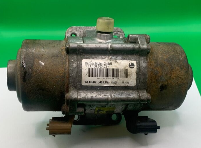
Selector motor unit
Manufactured by Getrag (with part numbers 1.61.100.003.03 or 1.61.100.003.04 depending on the revision) the selector motor unit its self sits on top of the gearbox leaning slightly towards the rear of the car and underneath the intake pipe (on a petrol) or the intercooler (on a diesel), it’s held on by four T40 bolts (which thanks to galvanic corrosion) will be insanely tight so be very careful not to strip the heads!
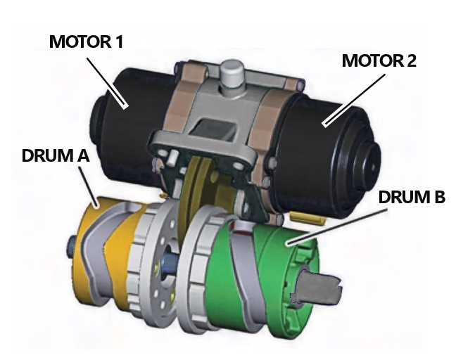
Comprising of a pair of motors (on either end) and two separate drive gears the unit is designed to drive corresponding selector drums (one for odd gears [1,3,5] and one for even gears [R,2,4] inside the gearbox.
Unlike the previous 450 model which had an angle / position sensor on the end of the selector shaft the later 451 has no positional sensors in the gearbox housing instead housed in the brush pack of each motor there is a small resin covered PCB with a pair of incremental sensors (based on SOT packaged Hall sensors) that detect the movement of the stator contacts enabling the TCM (transmission control module) to detect not just the direction of rotation but how many degrees the motor has rotated:
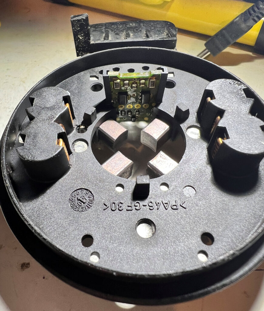
When the TCM performs a selector teach-in it will first wind the motors out in both clockwise and anti-clockwise directions until they stop and from the number of pulses generated by the incremental sensors it can calculate exactly how far a full stop-stop rotation is of each drum and thus at which relative position each resulting gear is.
TCM / Motor Pin-outs
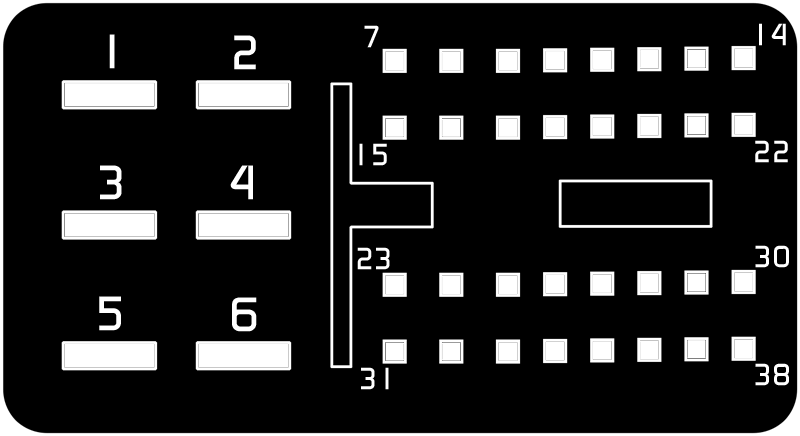
| Motor 1 Pin | TCM (Left) Pin | Colour | Function |
| 1 | 2 | Blue | Motor 1 GND |
| 2 | 10 | White/Red | Sensor PCB +VE |
| 3 | 26 | Blue/Green | Sensor B Output |
| 4 | 18 | Violet/Yellow | Sensor A Output |
| 5 | 34 | Brown/Yellow | Sensor PCB GND |
| 6 | 1 | Violet | Motor 1 +12V |
| Motor 2 Pin | TCM (Left) Pin | Colour | Function |
| 1 | 4 | Brown | Motor 2 GND |
| 2 | 11 | White/Brown | Sensor PCB +VE |
| 3 | 27 | Blue/Brown | Sensor B Output |
| 4 | 19 | Violet/Green | Sensor A Output |
| 5 | 35 | Brown/Violet | Sensor PCB GND |
| 6 | 3 | Red/Blue | Motor 2 + 12V |