
Terminals
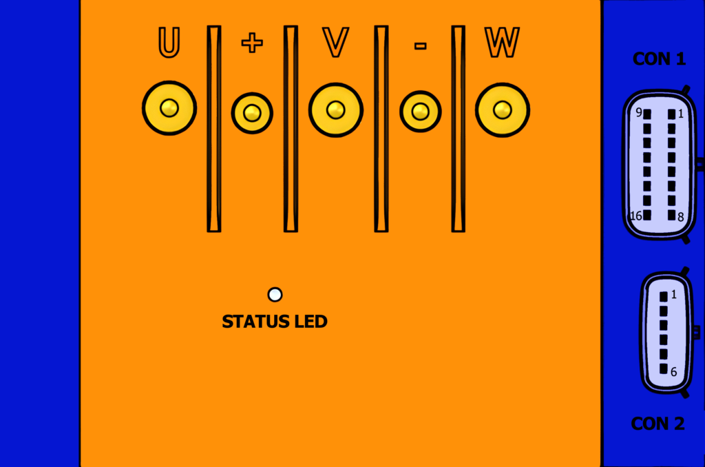
There are 5 screw terminals on the top of the unit which are for the motor phase wires and the battery.
| U | Motor phase wire U (Green) |
| + | Battery positive (36-72v) |
| V | Motor phase wire V (Yellow) |
| – | Battery negative |
| W | Phase Wire W (Blue) |
Molex Connectors
There are a pair of Molex connectors on the right hand side of the unit 1 x 16-pin MX150 and 1 x 6-pin MX150.
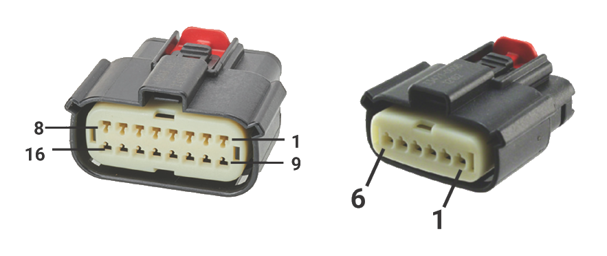
CON 1: 16-pin Molex MX150
| Pin # | Function | I/O Details | Continuous Current | Withstand Voltage | Notes |
|---|---|---|---|---|---|
| 1 | HDQ | Low-side Switch | 100 mA | 57 V | |
| 2 | Cruise | 5V Pulled-up, active low | 100 V | ||
| 3 | TTL-TX | 5V TTL | 9 V | ||
| 4 | 5V output | Polyfuse protected | 50 mA Shared | Shared output | |
| 5 | PFS | 5V Pulled-up, active low | 100 V | ||
| 6 | Brake 1 | 0-5V, Configurable 5V pull-up | 5.5 V | ||
| 7 | Throttle | 0-5V Pulled down | 5.5 V | ||
| 8 | 5V Output | Polyfuse protected | 50 mA Shared | Shared output | |
| 9 | Key In / Ignition | Connect to Battery positive to power on | 400 mA | 95 V | Requires B+ out connection, may draw up to 100 mA |
| 10 | CAN-L | 5V CAN | 20 V | Configurable 120 Ω termination resistor | |
| 11 | CAN-H | 5V CAN | 20 V | Configurable 120 Ω termination resistor | |
| 12 | ABMS | 0-10V Pulled down | 11.5 V | ||
| 13 | TTL-RX | 5V TTL | 9 V | ||
| 14 | Signal GND | 400 mA shared | 400 mA max shared with all GNDs | ||
| 15 | Signal GND | 400 mA shared | 400 mA max shared with all GNDs | ||
| 16 | 12V Output | Polyfuse protected | 50 mA | 47.5 V |
CON 2: 6-pin Molex MX150 (Hall Sensors)
| Pin # | Function | I/O Details | Continuous Current | Withstand Voltage | Notes |
|---|---|---|---|---|---|
| 1 | Hall 5V | 100 mA | 47.5 V | ||
| 2 | Hall GND | Polyfuse protected | 100 mA | ||
| 3 | Hall A (Yellow) | 5V Pulled-up, active low | 100 V | ||
| 4 | Hall B (Green) | 5V Pulled-up, active low | 100 V | ||
| 5 | Hall C (Blue) | 5V Pulled-up, active low | 100 V | ||
| 6 | Brake 2 | 0-5V, Configurable 5V pull-up | 5.5 V |
Programming ASI BAC Controllers
If you want to build your own DIY USB programming cable please check out this article.